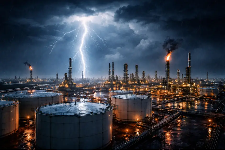
On November 6, 2026, lightning struck a home in Bay Shore, New York. Fire officials told CBS New York the strike hit an air-conditioning unit, blowing out windows and damaging the roof (CBS New York). Firefighters found no fire inside at first. Roughly two hours later a second call brought them back, and they found a fire in the attic (PIX11). The path the fire took has not been reported.
The incident is residential, but the engineering point applies to any structure: the point of attachment says little about how far a strike’s effects reach. Current and overvoltages reach well beyond it, affecting both the building and the internal systems a facility depends on. IEC 62305-2:2024 addresses those wider consequences, and it does so differently from the 2010 edition.
Lightning Damage Doesn’t Stop Where It Strikes
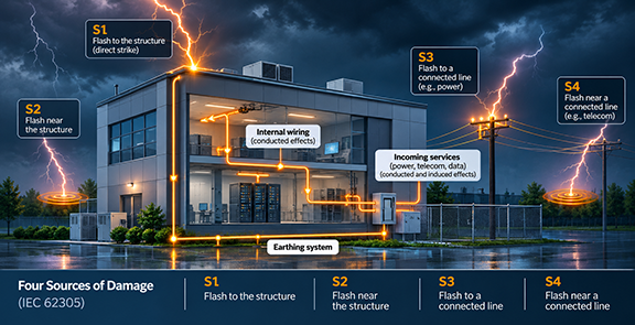
IEC 62305-1:2024 lists what a flash to a structure can cause. Some effects occur at or near the attachment point: mechanical damage, fire, or explosion from the arc, from ohmic heating of conductors, or from arc erosion. Others are carried away from it: fire or explosion triggered by sparks from resistive and inductive coupling and from partial lightning currents, and failure of internal systems due to the lightning electromagnetic impulse (LEMP).
Those effects reach equipment in two ways. Conducted effects travel through metallic connections, as part of the lightning current or the surge it creates flows along wiring, piping, and incoming lines. Induced effects need no connection: the changing magnetic field of the lightning current couples into conductor loops nearby. IEC 62305-4:2024 describes failures of electrical and electronic systems caused by both conducted and induced surges transmitted through connecting wiring. Under IEC 62305-1:2024, a flash to the structure produces surges by resistive and inductive coupling, while a flash to nearby ground couples inductively.
That is why the standard distinguishes four sources of damage by point of strike: flashes to the structure (S1), near it (S2), to a connected line (S3), and near a connected line (S4). Two of the four never touch the building. Flashes to or near incoming lines transmit current and overvoltages inside, with dangerous sparking generally at the line’s entrance point.
Physical damage and internal system failure
IEC 62305-2:2024 separates two causes of damage that matter here. Dangerous sparking that triggers fire or explosion is D2. Surges that cause failures of internal systems are D3, and they can come from any of the four sources.
The 2024 edition defines three types of loss: injury to human beings (L1), physical damage to the structure and its contents (L2), and failure of internal systems (L3). L3 concerns the function an internal system performs, not physical damage to the equipment. The standard notes that loss of service to the public is covered by frequency of damage and L3.
The two are evaluated differently and do not necessarily track each other. The standard’s own examples show how they interact: for a department store, IEC 62305-1:2024 lists failure of fire alarms resulting in delayed firefighting.
Frequency of damage in the 2024 edition
Where L3 can unacceptably impair the services internal systems provide, the standard adds a frequency of damage calculation to the risk calculation. Frequency of damage, F, is the sum of four partial frequencies, one per source of damage:
F = FC + FM + FW + FZ
Each is the number of dangerous events per year multiplied by a probability of damage. FW and FZ come entirely through the connected lines.
F is compared with a tolerable frequency, FT. Protection is necessary when F exceeds FT, and measures should bring F to no more than FT. The standard gives typical values of 0.1 per year for internal systems critical to their function and 1 per year for non-critical systems, and leaves the criticality judgment to the owner or manager of the structure. F is evaluated for the systems or equipment the owner wants to protect, zone by zone where the structure is divided into zones, and a system’s frequency of damage is that of its weakest equipment.
What changed from the 2010 edition
The 2010 edition had no frequency of damage calculation. It defined four types of loss: loss of human life (L1), loss of service to the public (L2), loss of cultural heritage (L3), and loss of economic value (L4), each assessed as risk. In 2024, loss of service is evaluated as a frequency against a tolerable value set by the owner, and the labels L2 and L3 mean different things. A 2010-era assessment does not map one-to-one onto the 2024 approach and should not be carried over without review.
What the assessment should capture
IEC 62305-2:2024 lists the factors that influence each risk component, and many sit well inside the walls. In practice, that puts several decisions in front of the engineer:
- Every connected line. The standard considers all lines connected to the structure. Shielding of external lines, isolating interfaces, and equipotential bonding all appear as factors, and flashes to or near metallic pipes count as a source of damage unless the pipes are bonded at the entrance. The assessment covers the structure and its connections; it does not model the utility network’s reliability.
- Internal pathways. Shielding and routing of internal lines affect induced overvoltages. Annex B (Table B.10) reduces the probability of damage when routing avoids large loops or cables are shielded.
- Which internal systems to evaluate. Identify the systems that carry the service. Equipment impulse withstand voltage and a coordinated SPD system both influence whether surges cause failure.
- What FT to use. The typical values are a starting point; a control system and an office network may justify different tolerances. Record who set the value and why.
- Building characteristics. Construction, fire sensitivity, and fire precautions feed into the physical damage components.
- Which component drives the result. When F exceeds FT, the standard’s procedure is to identify the salient partial frequencies and select measures that address them. A result dominated by FW calls for different measures than one dominated by FC.
None of these is visible from the roofline, and each can change the result. Documenting them also means later changes to wiring, equipment, or services are recognized as changes to the risk.
Where LRAplus fits
LRAplus® supports IEC 62305-2 assessments to both the 2010 and 2024 editions. Engineers define structures, divide them into zones, and specify connected lines, and for the 2024 edition the software calculates frequency of damage alongside risk, with the assessment exported as an editable report. The judgments above remain the engineer’s. Learn more about LRAplus.